
|
Hmm I still think I don't quite understand it. I blame Nissan's documentation This is my best current guess at how the whole thing operates, now: The lock unit supposedly
|
|||||||
|
|
LinkBack | Thread Tools | Display Modes |
 01-18-2012, 12:03 PM
|
#11 (permalink) |
|
A True Z Fanatic
 Join Date: Mar 2009
Location: Houston, TX
Posts: 4,024
Drives: too slow
Rep Power: 3595   |
Hmm I still think I don't quite understand it. I blame Nissan's documentation
 This is my best current guess at how the whole thing operates, now: This is my best current guess at how the whole thing operates, now:The lock unit supposedly has 7 pins on it. I'm giving them my own names for now since I still haven't found a pinout for connector M40, which is the actual connector at the lock unit: G1: Grounded permanently G2: Grounded permanently P1: power supply, switched by IPDM E/R P2: power supply, switched by BCM S1: feedback switch output: +12V when locked, 0V when unlocked S2: feedback switch output: 0V when locked, +12V when unlocked C: communication line between lock module and BCM Physical states: The steering lock can be in one of two physical states: locked or unlocked. Once it has switched to a given state, it will remain in that state until commanded to change, regardless of whether any power is supplied to the unit. No relay has to remain energized to maintain one of the states or anything like that. Power supply states: P1 (IPDM E/R): When ignition is ACC or ON, no voltage supplied. Temporarily supplies battery voltage for a short while after opening the driver's door when ignition is OFF, or after pushing the ignition button once when it's LOCKed. P2 (BCM): When ignition is OFF or ACC, +12V is supplied. When ignition is ON, it is not. None of this completely makes sense, but the bottom line is, when the ignition is ON, neither power supply pin gets voltage, so no change to steering lock status can occur. When ignition is not ON, one of the two power pins (or both) will give it power at the right times for it to respond to a lock or unlock command, somehow. It could be the case that P1 (IPDM E/R) only powers the feedback switches that drive S1 and S2, and P2 (BCM) powers everything else (the mini-controller that communicates with the BCM and actually moves the lock) Switch states: The S1 and S2 outputs are redundant inverted status outputs. They're almost certainly driven by physical switches that are tripped by the locking mechanism itself. In the unlocked state only one of them provides +12V, and in the locked state only the other does. If they're both +12V or both not +12V, that triggers a diagnostic failure. If they don't feedback that commands were followed correctly, that also triggers a diagnostic failure. Also of note: these are connected to both the IPDM E/R and the BCM, so for some reason both modules want to see this status. BCM Communication Line: This is the perplexing 7th pin "C": 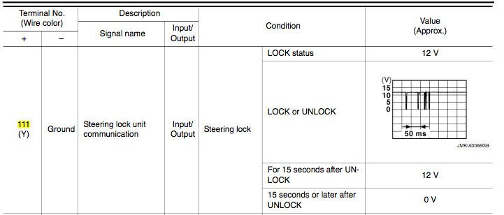 It's listed as both an input and an output for the BCM. It seems definitely sure that the BCM is who sends that little pulse train against a 12V background to send LOCK and UNLOCK commands, as an output. I misunderstood earlier that the pulse train came from the lock module. What really makes no sense is how any of this could be an input back to the BCM. Maybe it's mislabeled (from my point of view), and it's a BCM-output only, and the BCM drives it at +12V while LOCKED, and 0V when unlocked for 15+ seconds, and whenever it wants to send a command, it applies the +12V (if unlocked before) and then sends the pulse signal. I guess someone would have to figure out what the manual means by clipping onto this with a scope (or really, even a multi-meter would do, since the only complex bit is already documented in the diagram above). Last edited by wstar; 01-18-2012 at 12:21 PM. |

|

|
| Bookmarks |
|
|
 Similar Threads
|
||||
| Thread | Thread Starter | Forum | Replies | Last Post |
| Just joined the "Dreaded Steering Lock Club" | Timotay | New Forum Member | 2 | 03-06-2013 04:40 PM |
| Need a steering lock assembly!! | bfowlzr33 | Wanted | 8 | 01-02-2013 04:40 PM |
| Dreaded steering lock | Jim Roberts | Exterior & Interior | 2 | 12-12-2012 03:08 PM |
| Steering lock repair | fritz | DIY Section (Do-It-Yourself) | 38 | 02-22-2012 09:30 PM |


 61Likes


 Threaded Mode

