
|
Originally Posted by SPOHN Could you of only used the hoses from the front of the plenum and then routed to the catch can. Never really seen one that uses
|
|||||||
|
|
LinkBack | Thread Tools | Display Modes |
 04-24-2011, 10:03 PM
|
#6 (permalink) | |
|
A True Z Fanatic
 Join Date: Mar 2009
Location: Houston, TX
Posts: 4,024
Drives: too slow
Rep Power: 3595   |
Quote:
Here's the exploded view of the stock 370Z intake manifold collector from the service manual. What you want to pay attention to is the PCV connections, and the vacuum connections to the manifold in general. Aside from the big holes for the throttle bodies, there are 6 vacuum inlets on the manifold: two tiny EVAP inlets right next to the throttle bodies, a single brake booster connection in the rear (B), the hole that the MAP sensor plugs into (item 19, back right), and the two PCV connections (V-shaped inlets in the front/center, connected to PCV hoses numbered 10 and 12). 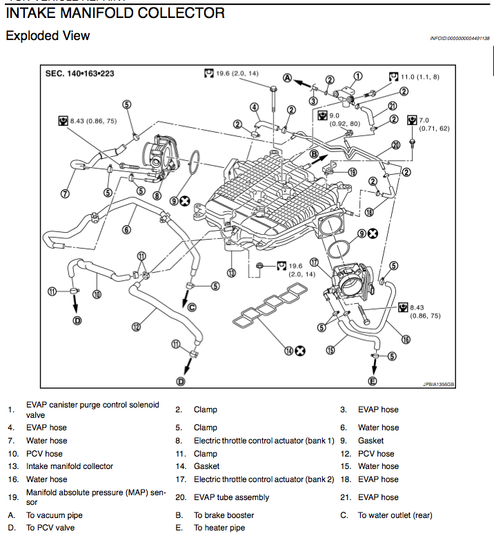 If you wanted to add an oil catch system to our stock car, you could go one of two routes. One way would be to install dual catch cans, with one spliced into each of PCV hoses 10 and 12 in the diagram. A simpler way would be to use a T-adapter to connect hoses 10 and 12 to a new single hose, send that to the catch can, and then connect the other side of the can to one of the original inlets, and cap off the other inlet. The M370's vacuum inlet configuration is different than our stock intake manifold collector to begin with. It still has the same two EVAP inlets next to the throttle bodies, but there's no hole for the MAP sensor, no front PCV inlets, and there's two rear inlets in the vicinity of the stock brake booster inlet. When you install the M370, you hook up the dual PCV hoses to a T-adapter to merge them, and run the new line around to the rear of the manifold. One of the rear connections goes straight to the brake booster as before, and the other one gets a second T-adapter, splitting it between the PCV line that came around from the front T-adapter, and a short hose that your MAP sensor is plugged into. It makes more sense looking at it visually (but note in this picture, they replaced the driver's side PCV hose (number 12 in the SM diagram) with one of their blue hoses):  In my DIY above, I've taken the long blue hose that's mostly hidden above, which wraps around on the left between the two T-connections in the front and the rear, and effectively spliced my can in the middle of that. So the can's inlet is connected (via a hose, a T-adapter, and then hoses 10 and 12 in the SM diagram) to the crankcase (twice, once at each valve cover), and the can's outlet goes to intake manifold vacuum. Last edited by wstar; 04-24-2011 at 10:09 PM. |
|

|

|
| Bookmarks |
|
|
 Similar Threads
|
||||
| Thread | Thread Starter | Forum | Replies | Last Post |
| Who's running a catch can? | J. Dub | Forced Induction | 58 | 06-13-2013 07:24 AM |
| Wtb m370 | Kastley85891 | Wanted | 0 | 04-12-2011 05:43 AM |
| M370 or some pulleys? | Kastley85891 | Intake/Exhaust | 33 | 03-24-2011 09:05 AM |
| 1000cc oil catch can | Seth G | DIY Section (Do-It-Yourself) | 0 | 03-10-2010 05:44 PM |


 2Likes


 Threaded Mode

