Well, as some of you know, this is something that has been in the works for some time. I believe the first conversation occurred about two years ago, when I saw this supercharger kit for the first time. The time has finally come for me to work my magic, and improve on some of the engineering done by Stillen.
The tear down was rather simple and straight forward. Pull the front bumper off, remove the water/air cooler, hoses, water pump and some additional plumbing. Once all that was removed, it was time to install the
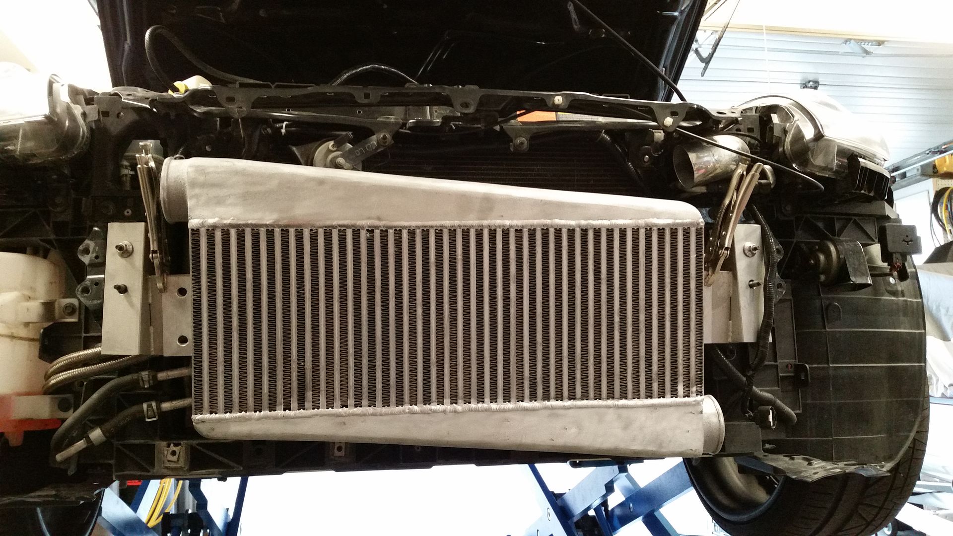
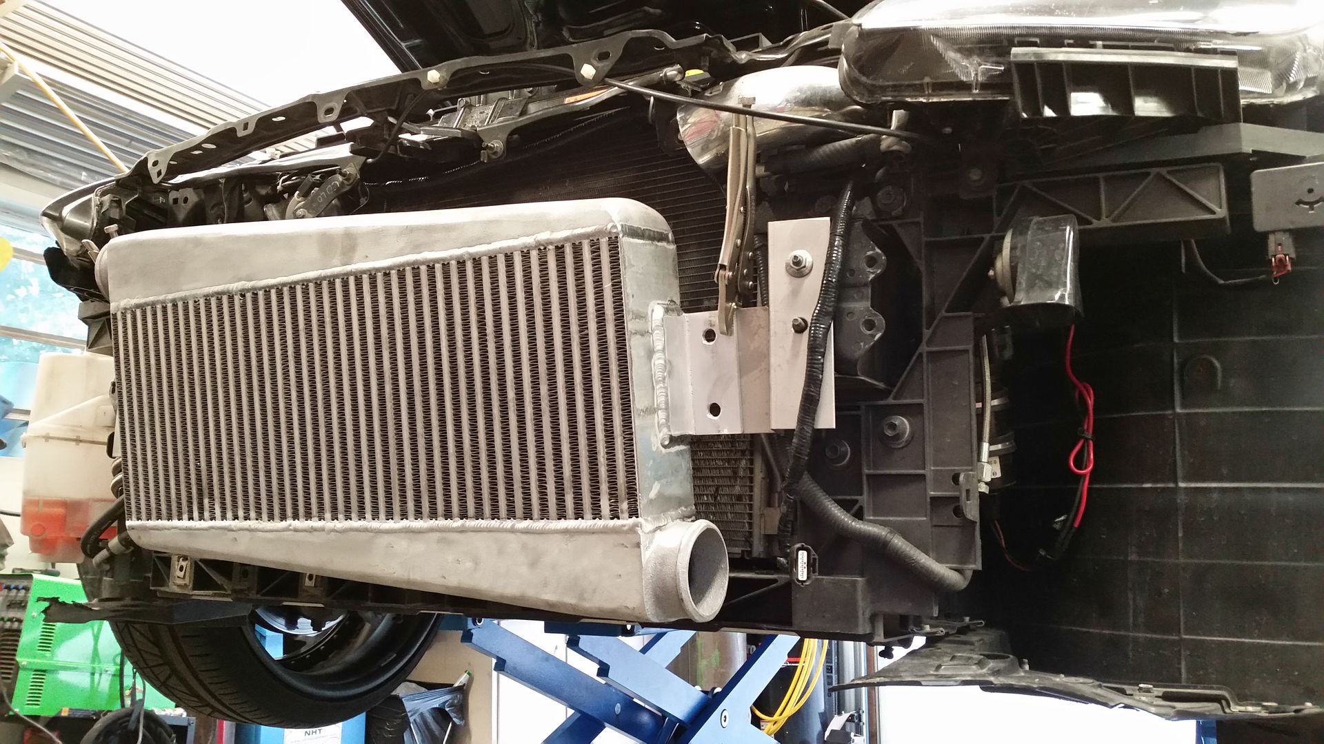
large air/air intercooler. This is the same intercooler core used on the Boosted Performance twin scroll turbo kits, but with a different end tank configuration. The core is capable of supporting 2,000cfm, so flow will never be an issue.
So step one, install the standard FMIC brackets from the BP twin scroll turbo kit, and mount the FMIC…rather simple:
The next big thing and my biggest concern with this set-up was the supercharger air intake. As it comes out of the box, a 3.5” to 2.5” reducer is used on the compressor inlet, which then goes to a 2.5” 90 degree aluminium
bend. That then goes to a Y and two small air filter. Knowing how little space there is, and me wanting to turn this in to a 3” intake, I figured it will be a challenge.
It actually went rather smooth. I used a 3.5” to 3.0” 90 degree silicone reducer, which was cut in such a way to allowed me to install it with the headlight removed (only 4 bolts):
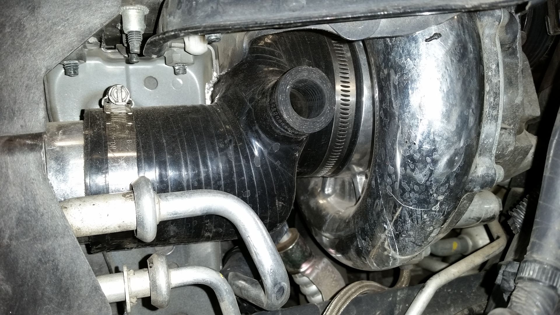
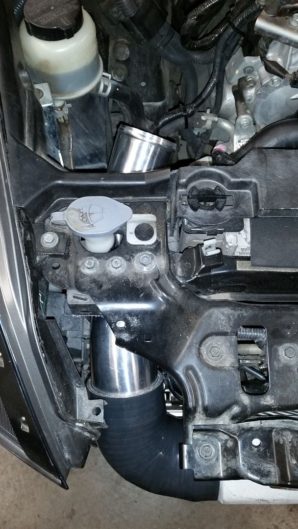
Not much room to work with:
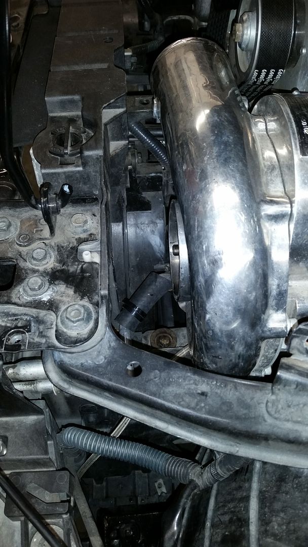
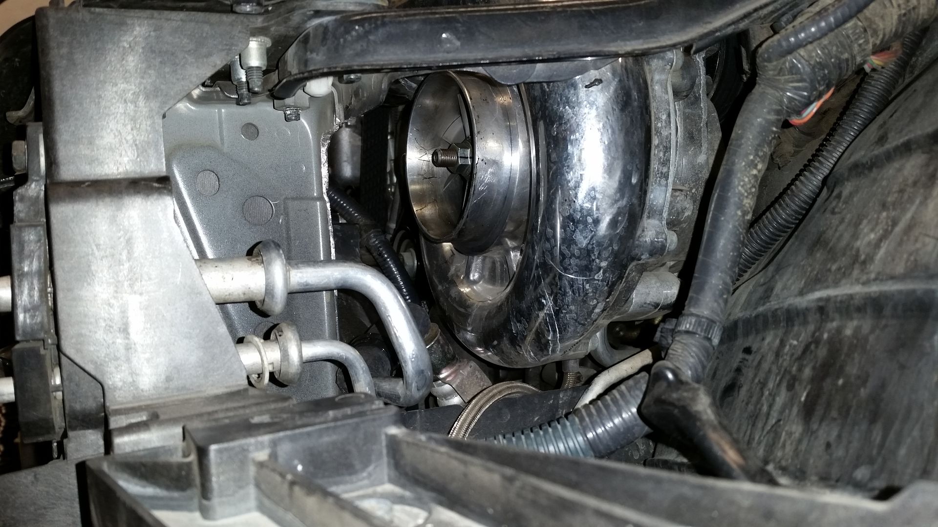
The improvement:
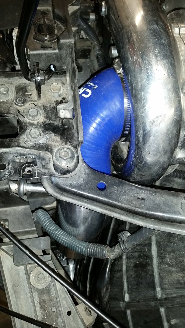
3” tube hanging in front of the driver side bumper, ready for an air filter:
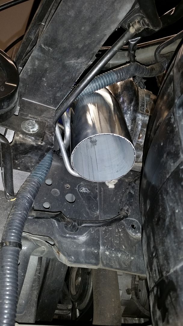
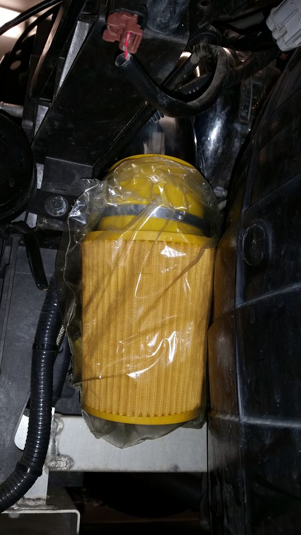
This configuration will allow for much better flow of air in to the supercharger. It also allows one to use a larger air filter, which is also a big plus. Should be getting some nice cold air in there now:
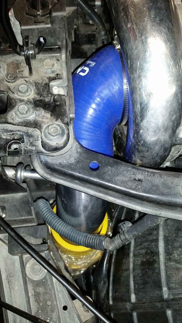
With the intake out of the way, I was able to move on to the S/C to IC piping. That was rather straight forward. A couple of the plastic pieces between the two fans needed to be cut, as well as one fan support on each fan (there are 8 total per fan, so it is not a big deal):
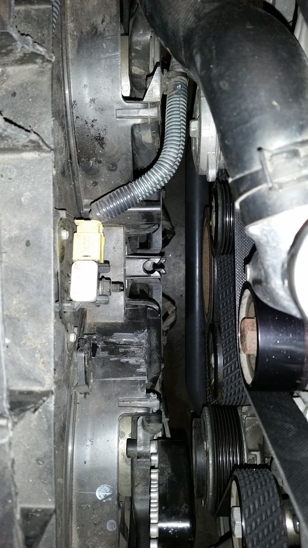
With that out of the way, I was able to rout a 2.5” charge pipe all the way down:
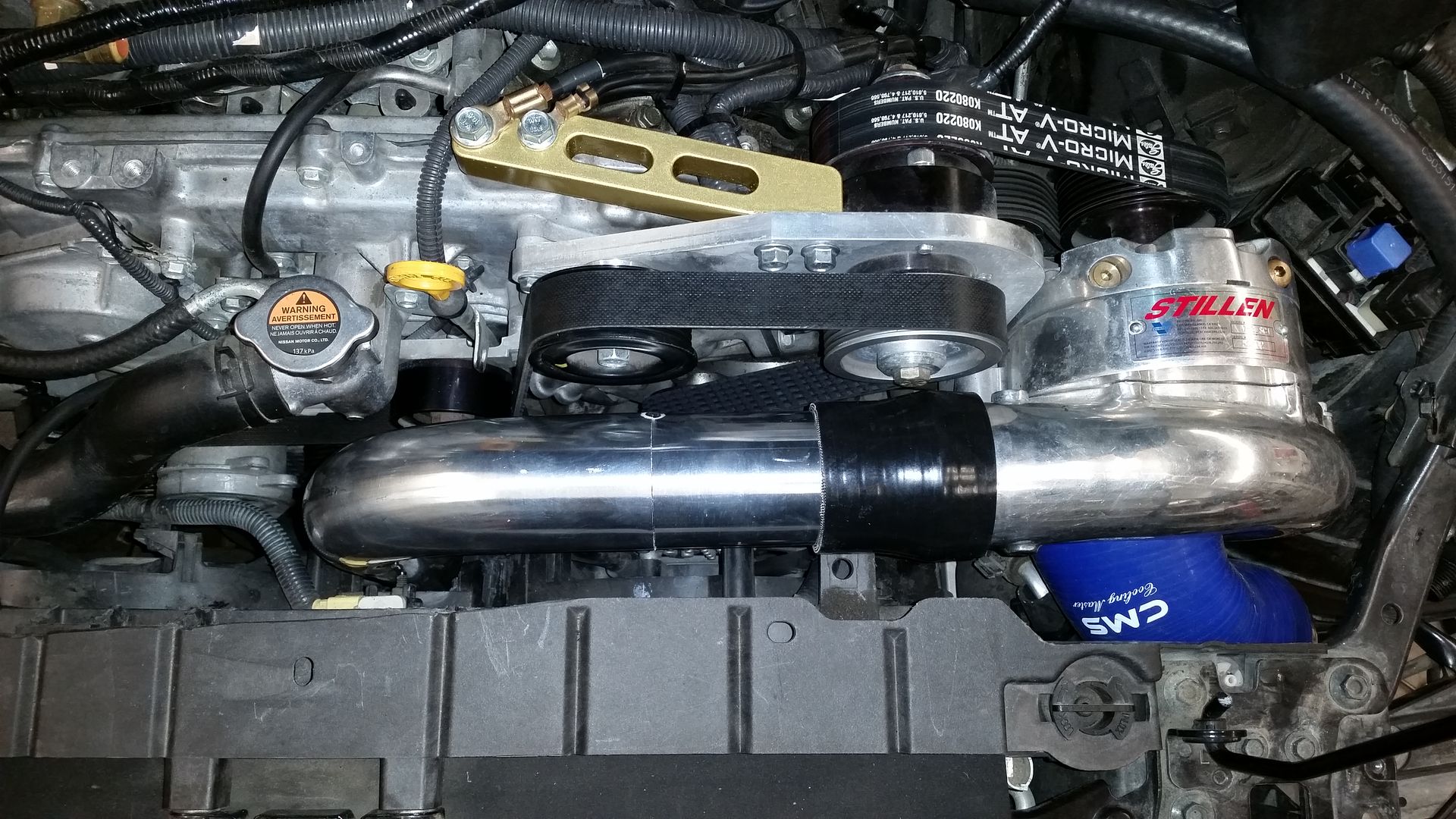
From there, it was rather straight forward to get to the IC inlet:
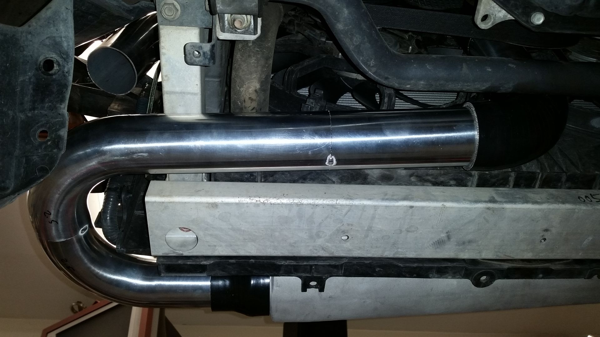
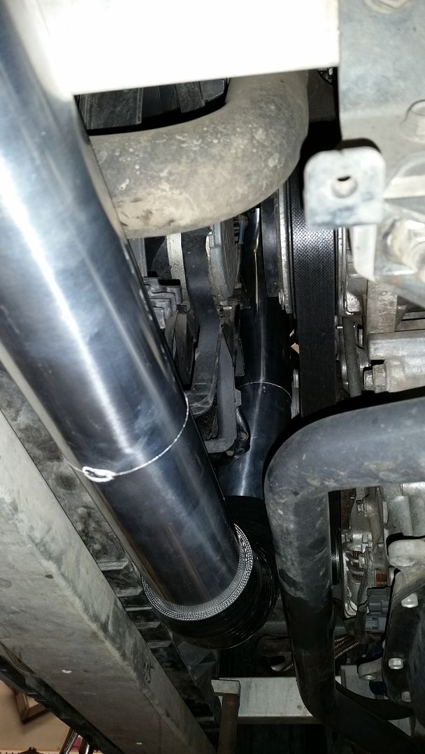
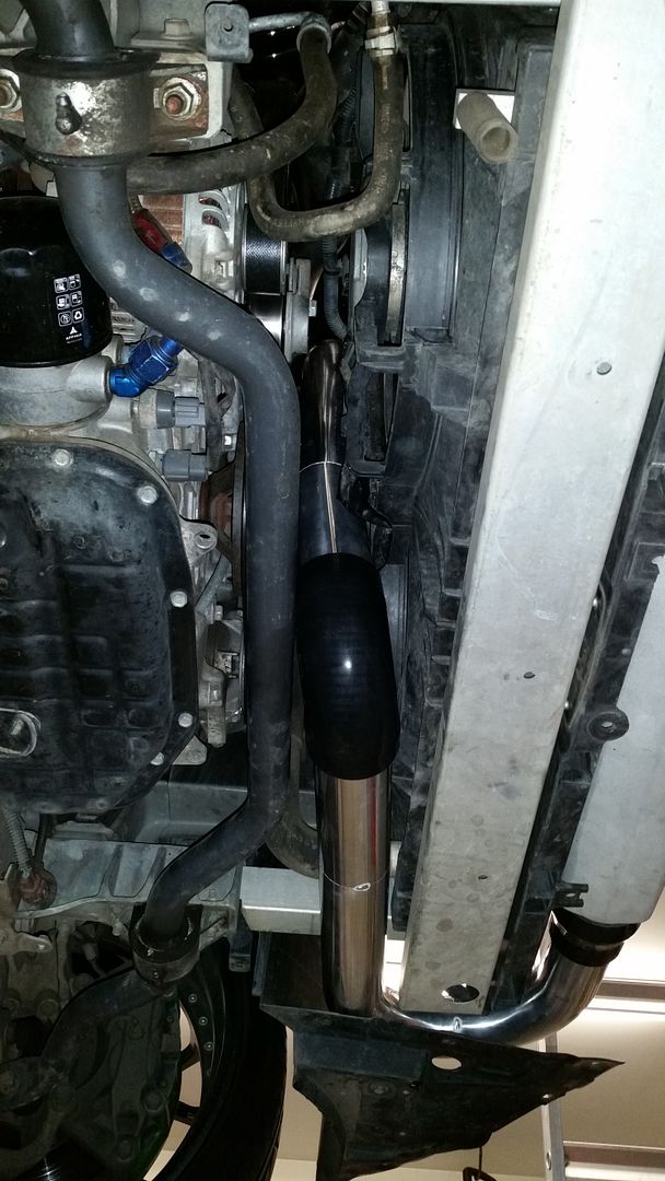
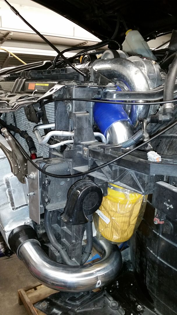
Next step, getting that nice cold air to the TB’s. 3” 90 degree out of the FMIC, and through to the engine bay:
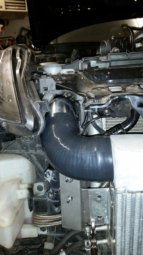
Moving on to the Y section, which is where I finished the night off.
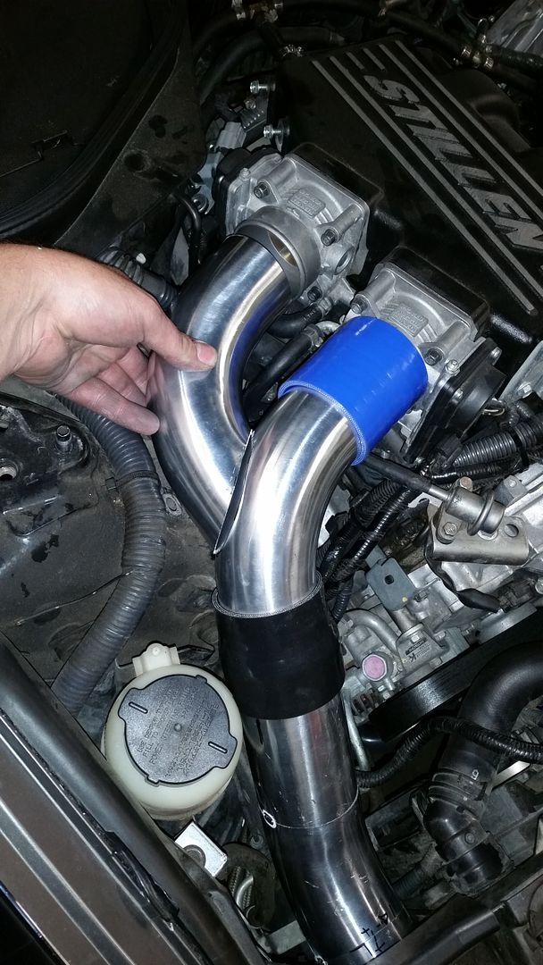
The plan is to install the MAF sensors in the 3” section of pipe just before the black coupler. This will allow for a proper reading of IAT’s, and will greatly improve the range of these sensors.
Some random shots:
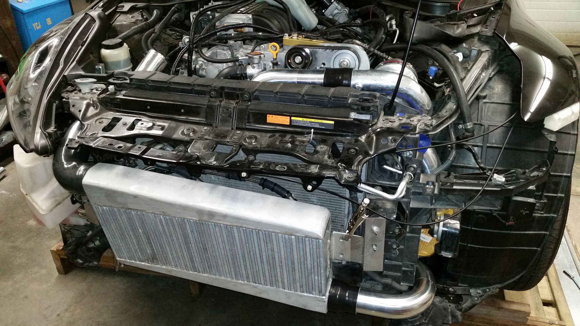
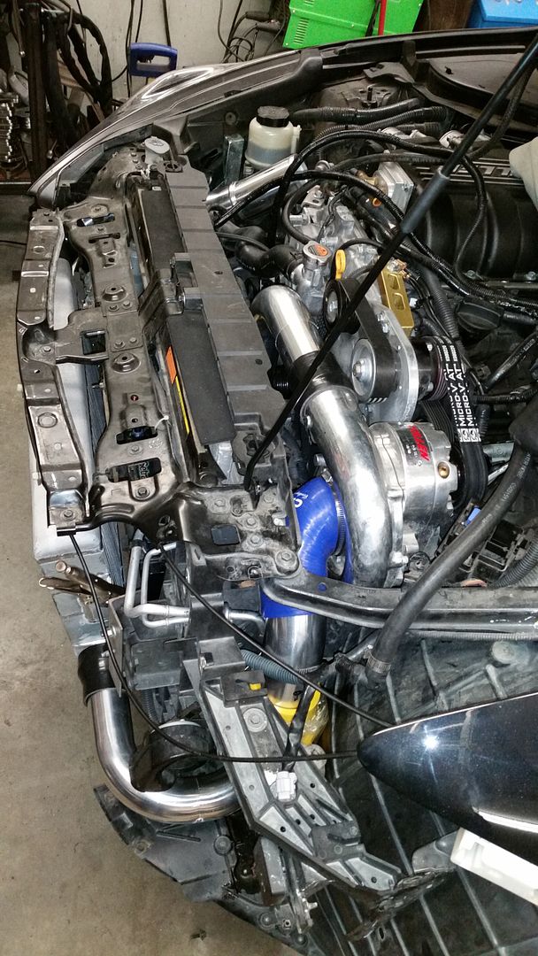
As it is built, with this air/air configuration, and a smaller pulley set. I don’t think 600whp is out of the ballpark with this kit. The head unit is certainly capable of pushing enough air, and now everything
around it will be able to support it. I will post some more pictures once I get back at this tonight.