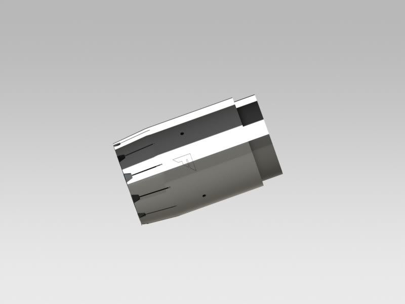
I've been in my head the last few hours and I got far enough to start throwing it in CAD.
The basic idea seen here is a tip assembly that slides over and butts up to the existing exhaust system, then is bolted in the two locations
from the inside via a hidden welded nut (weld nuts not shown yet). The outer section will be supported by the center support ring and 4 welded tabs that will support rivets.
This current model extends and points out past the existing exhaust tube by 2" (The dark grey ring at the edge of the tip is the tip inner ring which butts up to the lighter grey tubing with the oval cutout representing the existing exhaust tubing.)
The tip is .25" thick, ranging from 4.5" OD inner tubing to 5" OD outer tubing.
Can anyone get me the exact measurements of the oval bolt cutout, including its distance from the edge? How far back do the existing tips extend from the oval bolt hole? Out past the tip? Thanks.


