Quote:
Originally Posted by SPOHN

Could you of only used the hoses from the front of the plenum and then routed to the catch can. Never really seen one that uses the hoses from the rear of the plenum for that don't come from the crankcase. Could you explain that more?
|
So, to backtrack a little bit for anyone else reading this, I'll start with what the PCV (Positive Crankcase Ventilation) system does and how and why. Note that I'm not an expert on this: this is just my understanding from reading up on it and seeing how it works on cars I've owned. Corrections from more technically knowledgeable types welcome.
General PCV stuff:
The idea is that all combustion engines have a certain inevitable amount of blow-by, which is where combustion gasses from the cylinders leak past the piston rings and into the crank case in general. This is mostly fuel vapor. If you didn't have any PCV-like system at all, this would tend to build positive pressure in the crank-case, and eventually that pressure would find its way out by leaking past oil seals (such as at the crankshaft seals, etc), which in turn can lead to failure of those seals and oil leaks.
In some simple / old-school / dragster type setups, all that's done to alleviate this is they add some breathers to the valve covers of the engine. I suppose ideally, you'd put one on each valve cover with opposing check valves: one that filters in fresh air on one side of the engine, and one that vents crankcase gasses on the other. In this way you keep the air in the crankcase "fresh", and the pressure normalized. While the actual blowby gasses you're trying to vent off are mostly fuel vapor, in practice you tend to get a fair amount of oil vapor mixed in as well (from all the oil slinging around in the crankcase in general).
In modern pollution-controlled vehicles like ours, the PCV system does this in a slightly more complicated way. It uses some tricky little mechanical pressure-regulating valves to regulate everything at the PCV connections. On our car specifically, we have a total of four PCV connections at the valve covers. Each side has its own PCV inlet and outlet. The inlets are connected to your air intake tubes, drawing from the same filtered air the engine breathes for combustion. The outlets are connected to intake manifold vacuum lines to draw out the nasty fuel/oil vapor buildup, and feeds it right back into your combustion system to try to burn it for emissions reasons, even though this ugly fuel/oil crankcase vapor mix really isn't an ideal fuel for your high performance engine.
From a performance perspective, these nasty PCV gasses are contributing to lowering the effective octane rating of your fuel:air mix in the cylinders, and gunking up your intake manifold and intake valves with stuff that leads to carbon/sludge buildup. The point of the oil catch can is to put something inline in those PCV crankcase->manifold lines that tries to condense out the oily vapor and retain it, keeping your intake system clean of this crap, while still correctly maintaining crankcase pressures.
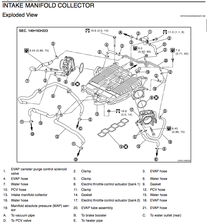
Here's the exploded view of the stock 370Z intake manifold collector from the service manual. What you want to pay attention to is the PCV connections, and the vacuum connections to the manifold in general. Aside from the big holes for the throttle bodies, there are 6 vacuum inlets on the manifold: two tiny EVAP inlets right next to the throttle bodies, a single brake booster connection in the rear (B), the hole that the MAP sensor plugs into (item 19, back right), and the two PCV connections (V-shaped inlets in the front/center, connected to PCV hoses numbered 10 and 12).

If you wanted to add an oil catch system to our stock car, you could go one of two routes. One way would be to install dual catch cans, with one spliced into each of PCV hoses 10 and 12 in the diagram. A simpler way would be to use a T-adapter to connect hoses 10 and 12 to a new single hose, send that to the catch can, and then connect the other side of the can to one of the original inlets, and cap off the other inlet.
The M370's vacuum inlet configuration is different than our stock intake manifold collector to begin with. It still has the same two EVAP inlets next to the throttle bodies, but there's no hole for the MAP sensor, no front PCV inlets, and there's two rear inlets in the vicinity of the stock brake booster inlet. When you install the M370, you hook up the dual PCV hoses to a T-adapter to merge them, and run the new line around to the rear of the manifold. One of the rear connections goes straight to the brake booster as before, and the other one gets a second T-adapter, splitting it between the PCV line that came around from the front T-adapter, and a short hose that your MAP sensor is plugged into. It makes more sense looking at it visually (but note in this picture, they replaced the driver's side PCV hose (number 12 in the SM diagram) with one of their blue hoses):

In my DIY above, I've taken the long blue hose that's mostly hidden above, which wraps around on the left between the two T-connections in the front and the rear, and effectively spliced my can in the middle of that. So the can's inlet is connected (via a hose, a T-adapter, and then hoses 10 and 12 in the SM diagram) to the crankcase (twice, once at each valve cover), and the can's outlet goes to intake manifold vacuum.